In order to understand QB64, you must first know what BASIC is
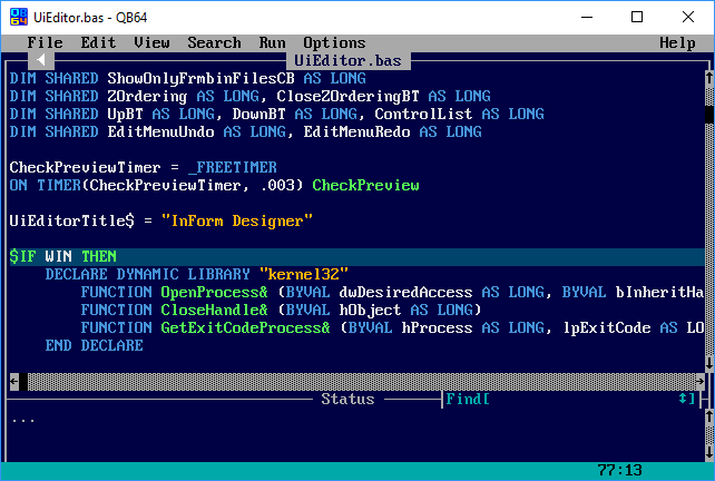
BASIC is a programming language developed in the late 60s and early 70s, becoming a mainstay as one of, if not the most influential programming languages of all time during the 80s. It was created to be a simple programming language that could be extremely easy to learn, but still really powerful as we'll soon see. During it's reign, an IDE called "Quick BASIC", or QBasic for short was created for DOS, accelerating BASIC's popularity and accessibility. Decades later, QBasic became the influence for QB64, a BASIC IDE for the 2000s. This became my IDE of choice, due to the modern OS compiling it brings, and it's simple project setup.
Although being built for 64 bit systems, QB64 doesn't give you many more capabilities that BASIC would have given you back in the day. However, it does bring benefits in the realm of graphics, but this did not impede the project or learning experience.
More information about QB64 and it's capabilities can be found at the QB64 homepage
What is 3D Rasterization?
3D Rasterization is a technique for drawing 3D scenes to a raster
Rasterization in general is the practice of mapping vector graphics to a raster. A raster, like a screen, tends to be a list of colors, or 'pixels'.
In 3D rasterization, these vector graphics are 3D objects projected onto a 2D plane, usually triangles onto a cross section of a virtual camera's viewport.
That is, given a list of 3d objects and attributes of each of those objects, 3d rasterizing is a method that takes in that information and results in an image with
a finite resolution.
Projecting and Rasterizing 3D objects is complicated to learn, but becomes simple to execute when understood.
There are numerous paths to achieve the desired result, and the paths this project took will be the only ones discussed here.
This project, like many others, relies on triangles for their efficiency in rasterization, use of vertex attributes,
and ability to form any other flat-faced 3d shape. There is a great deal of research and mathematical use behind triangles that makes them an
extremely powerful and versitile shape, while being very efficient to draw to a screen.
But before the project can display a full triangle, it needs to know how to project individual 3d points. It all comes down to some basic calculations,
but the origins and explanations behind which are fascinating. The process will be simplified by cutting out any unnecessary details and features, this will result in a less
interactive scene, but it cuts out many intermediate computations.
After the process knows how to transform and project triangles, it needs to know how to avoid drawing anything on top of something that's
supposed to be appear in front of it. Fortunately, it is an extremely simple process to include once the project is already drawing everything pixel-by-pixel.
Vector graphics consist of shapes and perfect lines, they are infinitely scalable and don't conform to a resolution, unlike images
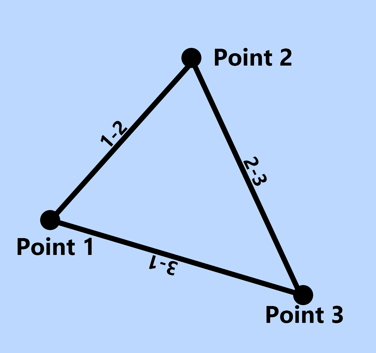
Before trying to understand the exact math and programming behind rasterizing a triangle, it's important to define triangles in these three ways.
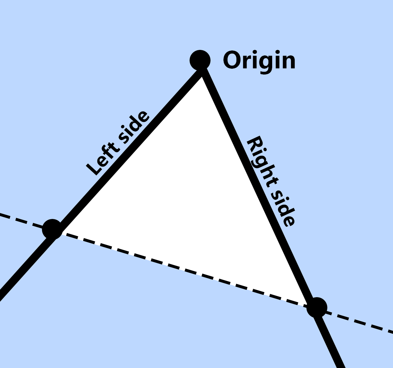
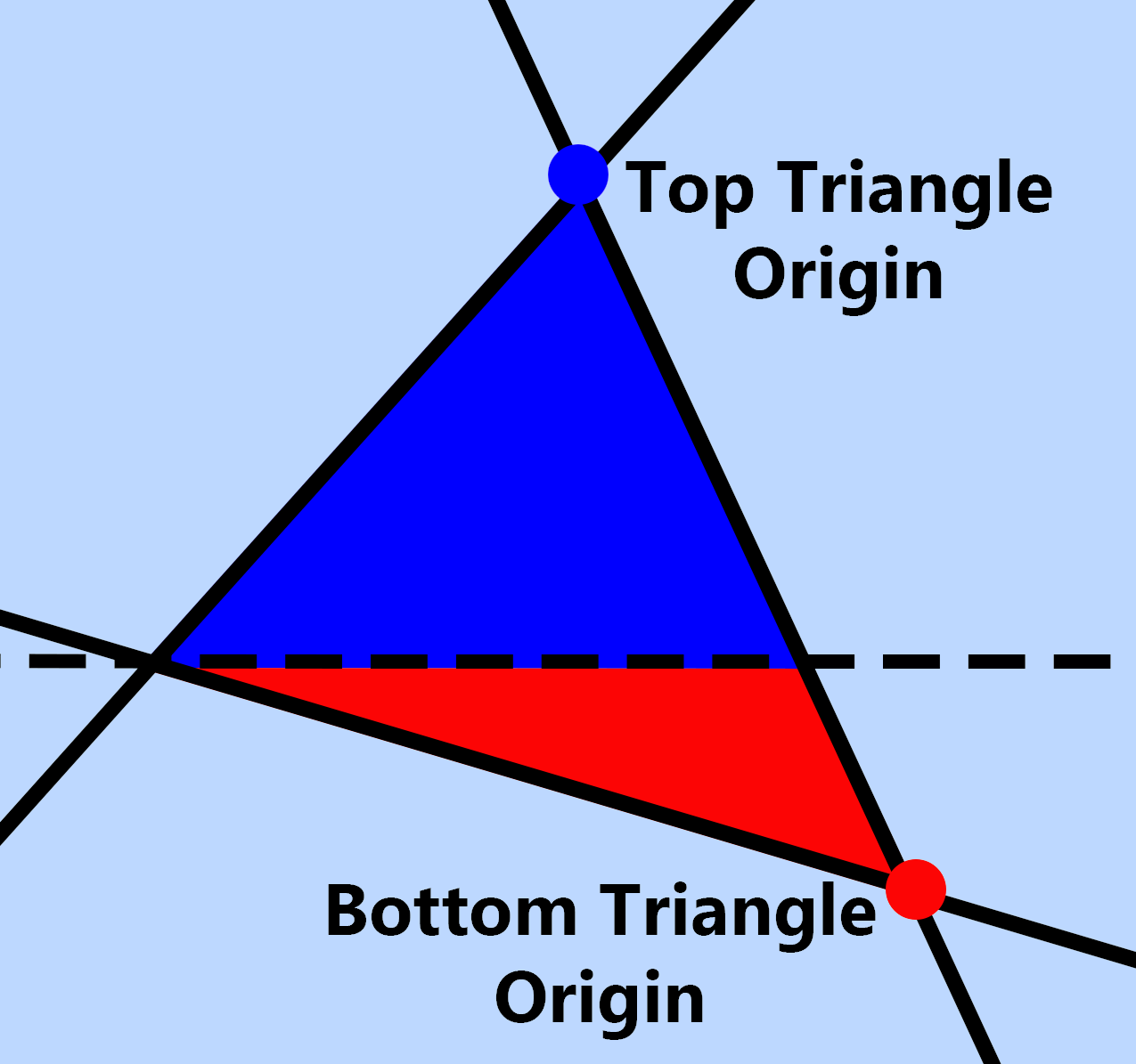
1: A set of 3 points, with lines connecting points 1 - 2, 2 - 3, and 3 - 1. 2: A single point with two lines jetting out from it, being filled until a terminating line. 3: A set of two triangles. With each of their terminating lines being horizontally flat.
With these three manners, we can split up the process of drawing a triangle into simple steps.
Firstly, drawing a triangle with a flat terminating line is much easier than one with a slanted terminating line.
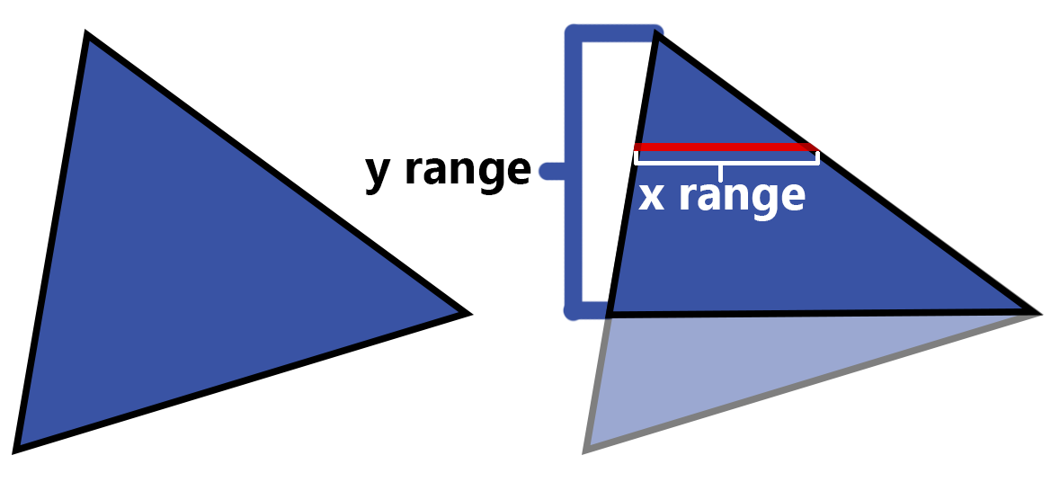
That is because, given a triangle of this manner, we can loop through every y position from the terminating line to the source.
And given a y-value in a triangle, we can find the range of x values that form a horizontal slice of the triangle.
Knowing this, we can write the processes for a flat-terminating triangle and be able to draw any triangle
given that we can split it into it's top-triangle and bottom triangle as defined by definition #3.
To know each x value, we can consider the two lines that run through the origin, as defined by definition #2.
Note that a line is given by the equation: "y = mx + b", and rewritten, we can find x when given y, using "x = (y - b)/m".
With this in mind, we can solve for the x-values of either line running through the origin when given the y position.
Which can come straigh from our loop between the two y-limits of our triangles. We can simplify this however. We do not know b in our example, so let's replace this equation with
"x = (y-offset.y)/m + offset.x". This equation means that we are using the difference in y to find the difference in x, since we know that both x and y start at our offset.
From this idea of using the difference in y to find difference in x, we can simplify this process for the computer. For our end product, we will be looping through every pixel in a triangle,
and for every y position included in the triangle, we find the range of x values included for the equivelent horizontal slice. We can loop through all y values very easily by setting an initial y value
to the highest y coordiante of the triangle, and incrementing it until it surpasses the lowest y coordinate of the triangle. This is even easier with a horizontal-terminator triangle, as it just needs
to loop between the y coordinate of the origin and the y coordinate of the terminator.
This also makes calculating the x range much simpler. As we can set an initial x value to the x coordinate of the origin, and every time we increment the y value, we add 1/m to our x value.
We use 1/m as it is the derivative of "x = (y - origin.x)/m + origin.x" (more specifically the dx/dy). Essentially, the difference between "x = (y - origin.x)/m + origin.x" and "x = (y + 1 - origin.x)/m + origin.x"
is just 1/m.
In summary, we can draw a flat-terminating triangle by looping through it's included y values, and for y value,
finding the boundaries of x by solving for the x values of the left and right edge lines. We will call our two resulting x-values, "left x" and "right x".
We can find the slope of a line going through two points by calculating "m = (y2-y1)/(x2-x1)".
By calculating (x2-x1)/(y2-y1) instead of the original reciprocal, we can find the inverse slope or, in other words, the value we increment x by for every increment in y.
Given that, we simply loop through y values, finding the left and right x values along the way, and then loop between the left and right x in order
to get or set every pixel inside of the flat-terminating triangle.
LEFT = ORIGIN_X
RIGHT = ORIGIN_X
' Left and Right inverse slopes
LINVSLOPE = ( TERMINATOR_LEFT - ORIGIN_X ) / ( TERMINATOR_Y - ORIGIN_Y ) RINVSLOPE = ( TERMINATOR_RIGHT - ORIGIN_X ) / ( TERMINATOR_Y - ORIGIN_Y ) For Y = ORIGIN_Y To TERMINATOR_Y
LEFT += LINVSLOPE
RIGHT += RINVSLOPE
For X = LEFT To RIGHT
Set Pixel ( X , Y ) Next
Next
Given that we can now draw a triangle with a flat terminator as detailed above,
we need to then check if any given triangle has a horizontally-flat edge somewhere, drawing it using that method if it does,
and forming two flat-terminating triangles out of it if it doesn't. We can find this by splitting the given triangle horizontally along the middle-y coordinate. What is meant by this, is
finding which of the 3 points of the triangle lies in between the other two in terms of y values, and setting that as our y coordinate to split on.
In BASIC, there is no quick easy way to find this middle point, so we shall insert a series of checks.
In order to define the two triangles, we need to find a missing point on the line opposite of our middle point. And we have two things in order to do that,
we have the line that the point lies on, and the y position of the point. Using our x = (y - b) / m, we can solve for x.
Thinking of our slope in terms of changes in y related to changes in x, we can find our new x with "x = (y - y1) * m + x1". With (y1, x1) being either end point of our target line,
and m being the inverse slope; (x2 - x1)/(y2 - y1). This shows us our mystery point to be ((middlePoint.y-y1)*(x2-x1)/(y2-y1) + x1, middlePoint.y). While this is rather hefty in terms of a small computation,
it is only needed at maximum once for every time a triangle is drawn.
Try moving points around, observe what calculations are used to find (x, y)
Given all this, we can now draw any 2 dimensional triangle to the screen by splitting it into two flat-terminating triangles and drawing each of them with our flat-terminating triangle method.
Here is a code example with comments.
Sub flat_triangle ( x1 , y1 , x2 , x3 , term ) 'A is ( x1 , y1 ) , B is ( x2 , term ) , and C is ( x3 , term ) 'Declare inverse slops from a to b , and a to c
a_m = ( x2 - x1 ) / ( term - y1 ) b_m = ( x3 - x1 ) / ( term - y1 ) 'Declare the y "scanline" , set it to the terminator and work up to the origin
y = term
'Declare the two x values that walk the lines from the terminator to the origin
lx = x2
rx = x3
'Sign dictates whether rx is in the positive-x or negative-x direction from lx
xsign = Sgn ( rx-lx ) 'Same with ysign and y1-terminator
ysign = Sgn ( y1-term ) Do
'Declare the current x position that we will plot a pixel at
x = lx
Do
PSet ( x , y ) 'Set the pixel! ( QB64 method , requires 32 bit screen mode ) 'Increment x in the direction of rx
x = x + xsign
'Do this until the current x surpasses rx.
'Sign is checked in order to tell if x surpasses rx when it's greater , or lower
Loop While ( ( xsign = 1 And x < rx ) Or ( xsign = -1 And x > rx ) ) 'Increment y towards the origin
y = y + ysign
'Travel lx down line a , ( x2 , bottom ) -> ( x1 , y1 ) , and rx down line b
lx = lx + a_m * ysign
rx = rx + b_m * ysign
Loop While ( ( ysign = 1 And y < y1 ) Or ( ysign = -1 And y > y1 ) ) End Sub
Sub triangle ( x1 , y1 , x2 , y2 , x3 , y3 ) Dim m As Double
'If any two y coordinates are equal , then draw a flat triangle
If y1 = y2 Then
Call flat_triangle ( x3 , y3 , x1 , x2 , y1 ) : GoTo ft2dskip
ElseIf y2 = y3 Then
Call flat_triangle ( x1 , y1 , x2 , x3 , y2 ) : GoTo ft2dskip
ElseIf y3 = y1 Then
Call flat_triangle ( x2 , y2 , x1 , x3 , y1 ) : GoTo ft2dskip
End If
'Find the middle y-coordinate and split the triangle into 2 flat triangles
'And for each point , find the missing x value opposite of the middle
'During the explanation , I used the top point to find the missing midpoint.
'But it can be found even if we interchange the bottom and top point , 'so we can avoid figuring out which is the top and find the midpoint directly from
'one of the non-middle points
If ( y1 < y2 And y1 > y3 ) Or ( y1 > y2 And y1 < y3 ) Then
m = x2 + ( y1 - y2 ) * ( x3 - x2 ) / ( y3 - y2 ) Call flat_triangle ( x3 , y3 , x1 , m , y1 ) Call flat_triangle ( x2 , y2 , x1 , m , y1 ) GoTo ft2dskip
ElseIf ( y2 < y1 And y2 > y3 ) Or ( y2 > y1 And y2 < y3 ) Then
m = x1 + ( y2 - y1 ) * ( x3 - x1 ) / ( y3 - y1 ) Call flat_triangle ( x3 , y3 , x2 , m , y2 ) Call flat_triangle ( x1 , y1 , x2 , m , y2 ) GoTo ft2dskip
ElseIf ( y3 < y1 And y3 > y2 ) Or ( y3 > y1 And y3 < y2 ) Then
m = x1 + ( y3 - y1 ) * ( x2 - x1 ) / ( y2 - y1 ) Call flat_triangle ( x2 , y2 , x3 , m , y3 ) Call flat_triangle ( x1 , y1 , x3 , m , y3 ) End If
ft2dskip:
End Sub
The only time a triangle can't be split up this way, is if it already has a horizontally-flat edge; In the program we will test for these cases to avoid errors and unecessary computations.
If y1 < y2 and y1 > y3 Then y1 is middle y2 is bottom (y-positive is down) y3 is top
Etc.
Barycentric Coordinates
Barycentric coordinates are a system of coordinates that, given a triangle ΔABC and a point P inside that triangle, defines it's values as the areas of subtriangles ΔPBC, ΔAPC, and ΔABP all divided by the total area of ΔABC.
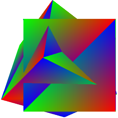
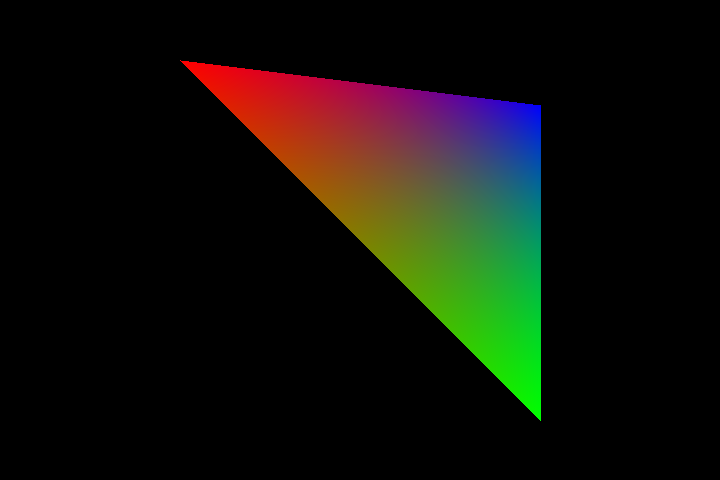
This is used to blend vertex attributes, attributes given each vertice of a triangle, such as color or depth. Barycentric coordinates are needed for depth, but as in the mention of color, we can use
them to make our triangles look a little more interesting. Say that for point A of our triangle, we give it an attribute for color, and set it to red. Point B set to green, and point C to blue.
Using barycentric coordinates, we can find the blended color for a point on the triangle. This creates the visual of a gradient where, as a point gets closer to point A, it appears more red. But closer to B or C,
it appears more green or blue.
The calculation of barycentric coordinates, notated as UV and W.
$$\left(U, V, W\right) = \left(\frac{\mathrm{area of} ΔPBC}{\mathrm{area of} ΔABC}, \frac{\mathrm{area of} ΔAPC}{\mathrm{area of} ΔABC}, \frac{\mathrm{area of} ΔABP}{\mathrm{area of} ΔABC}\right).$$
And for our color mixing example,
$$COLOR = RED * U + GREEN * V + BLUE * W$$
Triangle Area via Cross Product
In order to solve barycentric coordinates of a point/pixel in a triangle, we need an efficient way to solve the area of a triangle. The method used for this is the cross product.
The cross product is an operation that takes in two vectors, and it returns a 3rd vector that is perpendicular to the input vectors. A result of the cross product is that the output vector
has a length (magnitude) equivelant to the area of a parallelogram formed by the two input vectors. Now what "parallelogram formed by the two input vectors" means is that if you picture a copy of
each vector placed at the tip of the other vector, it forms a parallelogram. And this is what we will get the area of.
Working in 2 dimensions, the cross product is extremely easy to compute. Given that the computation returns a vector perpendicular to the two input vectors, and our input vectors only exist
on the x-y plane, we can conclude that the cross product will only point in either z-direction, meaning that we only have to calculate the z-component of any 2d cross product. Furthermore, the area
of a triangle formed by the two input vectors is half the area of the parallelogram. This is easier seen visually, however it is evident that cutting a parallelogram diagonally across two of it's vertices
splits it in half. The triangles formed are similar as they have the same length sides, meaning that two times the area of one of the triangles gives you the area of the parallelogram.
Calculating the z component of the cross product between two 2D vectors is as follows:
$$z = a_x * b_y - a_y * b_x$$
Or, given 3 points;
$$\left(x_2-x_1\right) * \left(y_3-y_1\right) - \left(y_2-y_1\right) * \left(x_3-x_1\right) $$
Thus the triangle area from three points;
$$\frac{\left(x_2-x_1\right) * \left(y_3-y_1\right) - \left(y_2-y_1\right) * \left(x_3-x_1\right)}{2}$$
When taking the barycentric coordinates (u, v, w), we procedurally check new points of the triangle with the point we want to sample inside the triangle.
In our process, that would be the x and y of the pixel we are setting; \(p_x\) and \(p_y\). In order to preserve vertex order, we must write the calculations in the way specified below.
Think of it as, for every next barycentric coordinate, we increment every point we're subtracting p from; e.i. \(x_1 -> x_2; x_2 -> x_3; x_3 -> x_1\). The following gives us \(a\) as the
full area of the triangle triangle, as well as \(u\), \(v\), and \(w\) as the barycentric coordinates, in the range (0-1).
$$a = \frac{\left(x_3-x_1\right) * \left(y_2-y_1\right) - \left(y_3-y_1\right) * \left(x_2-x_1\right)}{2}$$
$$u = \frac{\left(x_3-p_x\right) * \left(y_2-p_y\right) - \left(y_3-p_y\right) * \left(x_2-p_x\right)}{2a}$$
$$v = \frac{\left(x_1-p_x\right) * \left(y_3-p_y\right) - \left(y_1-p_y\right) * \left(x_3-p_x\right)}{2a}$$
$$w = \frac{\left(x_2-p_x\right) * \left(y_1-p_y\right) - \left(y_2-p_y\right) * \left(x_1-p_x\right)}{2a}$$
The resulting \(u\), \(v\), and \(w\) can be thought of as percentages declaring how close a point is two the 3 vertices of a triangle. For instance,
if \(u = 1\), then the point lies at vertex \(a\), with the subtriangle for u being equal to the full triangle. But if \(u = 0\), the point
lies on the edge opposite to vertex \(a\), and should inherit none of \(a\)'s attributes.
Essentially, the attributes of any given point or pixel inside of a triangle is equal to the sum the attributes of each vertice, multiplied by their associated barycentric component. I.e;
$$pixel_{attribute} = a_{attribute} * u + b_{attribute} * v + c_{attribute} * w$$
Here is a visual example, where vertex \(a\) has a color attribute of red, \(b\) with green, and \(c\) with blue.
This allows us to step into the more modern territory of shading and triangle rasterization. For instance, if we give each vertice of a triangle coordinates that represent a point in an image,
it allows us to blend these coordinates across the triangle, and use them to grab data from an image. This is known as texture mapping. Here is an example of a rainbow pattern being mapped onto a triangle.
If you do not have an understanding of how this would be put together, here is a code example of a function that takes in 3 points of a triangle, and a 4th point to get the Barycentric coordinates of.
Function getU ( ax , ay , bx , by , cx , cy , px , py ) area = ( ( cx - ax ) * ( by - ay ) - ( cy - ay ) * ( bx - ax ) ) * 0.5 ' Compute cross product divided by two
u = ( cx - px ) * ( by - px ) - ( cy - pc ) * ( bx - px ) getU = u / 2*area
End Function
Function getV ( ax , ay , bx , by , cx , cy , px , py ) area = ( ( cx - ax ) * ( by - ay ) - ( cy - ay ) * ( bx - ax ) ) * 0.5
v = ( ax - px ) * ( cy - px ) - ( ay - pc ) * ( cx - px ) getV = v / 2*area
End Function
Function getW ( ax , ay , bx , by , cx , cy , px , py ) area = ( ( cx - ax ) * ( by - ay ) - ( cy - ay ) * ( bx - ax ) ) * 0.5
w = ( bx - px ) * ( ay - px ) - ( by - pc ) * ( ax - px ) getW = w / 2*area
End Function
'For every pixel in triangle rasterizing...
'x1-2-3 and y1-2-3 are the triangle's vertices , with x and y being the current pixel's coords
Color _RGB ( 255 * getU ( x1 , y1 , x2 , y2 , x3 , y3 , x , y ) , 255 * getV ( x1 , y1 , x2 , y2 , x3 , y3 , x , y ) , 255 * getW ( x1 , y1 , x2 , y2 , x3 , y3 , x , y ) ) PSet ( x , y ) 'Paints the pixels of a triangle Red , green , and blue based on the barycentric coords.
For a more in-depth and general purpose approach, I recommend Grand Sanderson/3blue1brown's series:
Essence of Linear Algebra
It goes through everything visually and can teach anyone a general understanding of what Linear Algebra is.
Our usage of Linear Algebra revolves around using Matrices to transform Vectors. But firstly, we shall define those terms.
A Matrix, (plural Matrices) is a 2 dimensional series of numbers, with \(n\) number of columns and \(m\) number of rows. Matrices are typically used to describe a "transformation".
For instance, a matrix might stretch/scale all x values out by a factor of 2. And it would look like this;
$$\begin{bmatrix}2 & 0\\ 0 & 1\end{bmatrix}$$
With the computation looking like this.
$$x' = 2*x + 0*y$$
$$y' = 0*x + 1*y$$
This means that for any given x and y, the resulting x (\(x'\)) is two times the input x, and the resulting y \(y'\)) staying the same as the input y.
A vector, in the way we visualize it, is an arrow with the tail end sitting on the origin (the coordinates 0, 0), and the tip sitting at
a given coordinate. A vector is typically only defined by its tip's coordinates, as the tail will never be anywhere besides the origin. However, a vector can also be thought of as just a point existing
at its defining coordinates. It's just that with that definition, it is harder to visualize transformations happening to it. But still keep note that vectors in 3d graphics are often used to just store
coordinates, but the same transformations can be applied to them.
These transformations happen through matrix multiplication. You can plug any vector or coordinate in and get a resulting coordinate
that follows the rules defined by the matrix. This is extremely useful in 3d graphics as it allows for all sorts of transformations and even traslations. We could then create a matrix
that rotates all vectors, or one that projects all input 3d vectors into 2 dimension. This idea of projection is extremely important, and will be discussed again shortly.
The Matrices used above are as follows
$$\begin{bmatrix}2 & 0\\ 0 & 1\end{bmatrix}$$
$$\begin{bmatrix}cos(90^{\circ}) & -sin(90^{\circ})\\sin(90^{\circ}) & cos(90^{\circ})\end{bmatrix}$$
And
$$\begin{bmatrix}1 & 1\\ 0 & 1\end{bmatrix}$$
The Matrices we use will be based off of Column Vectors. Meaning that we will write our vectors standing upright as so
$$\begin{bmatrix}x\\y\\z\\w\end{bmatrix}$$
This matters as the process of multiplying a Row Vector with a matrix, and a Column Vector with a matrix changes the output, even though
the only difference between Row and Column Vectors is notation.
$$\begin{bmatrix}x\\y\\z\\w\end{bmatrix}\begin{bmatrix}\color{red}a_0 & \color{red}a_1 & \color{red}a_2 & \color{red}a_3\\\color{green}b_0&\color{green}b_1&\color{green}b_2&\color{green}b_3\\\color{blue}c_0&\color{blue}c_1&\color{blue}c_2&\color{blue}c_3\\\color{yellow}d_0&\color{yellow}d_1&\color{yellow}d_2&\color{yellow}d_3\end{bmatrix}$$
$$=$$
$$x' = x\textcolor{red}{a_0} + y\textcolor{red}{a_1} + z\textcolor{red}{a_2} + w\textcolor{red}{a_3}$$
$$y' = x\textcolor{green}{b_0} + y\textcolor{green}{b_1} + z\textcolor{green}{b_2} + w\textcolor{green}{b_3}$$
$$z' = x\textcolor{blue}{c_0} + y\textcolor{blue}{c_1} + z\textcolor{blue}{c_2} + w\textcolor{blue}{c_3}$$
$$w' = x\textcolor{yellow}{d_0} + y\textcolor{yellow}{d_1} + z\textcolor{yellow}{d_2} + w\textcolor{yellow}{d_3}$$
$$\begin{bmatrix}x&y&z&w\end{bmatrix}\begin{bmatrix}\color{red}a_0 & \color{red}a_1 & \color{red}a_2 & \color{red}a_3\\\color{green}b_0&\color{green}b_1&\color{green}b_2&\color{green}b_3\\\color{blue}c_0&\color{blue}c_1&\color{blue}c_2&\color{blue}c_3\\\color{yellow}d_0&\color{yellow}d_1&\color{yellow}d_2&\color{yellow}d_3\end{bmatrix}$$
$$=$$
$$x' = x\textcolor{red}{a_0} + y\textcolor{green}{b_0} + z\textcolor{blue}{c_0} + w\textcolor{yellow}{d_0}$$
$$y' = x\textcolor{red}{a_1} + y\textcolor{green}{b_1} + z\textcolor{blue}{c_1} + w\textcolor{yellow}{d_1}$$
$$z' = x\textcolor{red}{a_2} + y\textcolor{green}{b_2} + z\textcolor{blue}{c_2} + w\textcolor{yellow}{d_2}$$
$$w' = x\textcolor{red}{a_3} + y\textcolor{green}{b_3} + z\textcolor{blue}{c_3} + w\textcolor{yellow}{d_3}$$
Projection in 3d graphics is the idea of transforming a vector from the 3d coordinate space into the 2d coordinate space, in a way that retains visual information that shows depth,
such as foreshortening. You may recall that your screen is a series of pixels given at a certain resolution. This can give you the coordinates for each pixel. Generally 2D integers coordinates,
such as (100, 240) or (145, 23). The 3d vectors used as an input for a 3D projector can use any kind of units. These could be integers or decimals at any given scale.
Our projector will transform these coordinates into "screenspace coordinates", coordinates ranging from (-1, -1, -1) to (1, 1, 1), in a way that preserves the window's display ratio
(i.e. 16:9, 4:3, 2:1, etc.) After doing so, it can bring the coordinates from 3d into 2d in a way that shows foreshortening. From there it must convert this range of numbers to actual
pixel coordinates in order to show the image we desire.
The first transforming Matrix we will use, is;
$$\begin{bmatrix}\color{red}F_x & 0 & 0 & 0\\0 & \color{red}F_y & 0 & 0\\0 & 0 & \color{yellow}Z_m & \color{yellow}Z_a \\ 0 & 0 & \color{blue}-1 & 0 \\\end{bmatrix}$$
For foreshortening, we will use:
$$\begin{bmatrix}\color{red}1/z&0\\0&\color{red}1/z\end{bmatrix}$$
Or, simply:
$$x' = x / z$$
$$y' = y / z$$
And finally, transforming the coordinates into pixel coordinates; (The input z is required to be 1; \(S_w\) and \(S_h\) are the width and height of whatever is being displayed to.)
$$\begin{bmatrix}\color{red}\frac{1}{2}S_w & 0 & \color{yellow}\frac{1}{2}S_w \\ 0 & \color{red}\frac{1}{2}S_h & \color{yellow}\frac{1}{2}S_h \\ 0 & 0 & 1 \end{bmatrix}$$
Or even more simply;
$$x' = \frac{S_w}{2}\left(x + 1\right)$$
$$y' = \frac{S_h}{2}\left(y + 1\right)$$
If we expand each of these transformations, we may simplify things down into an easy-to-digest calculation.
Our first matrix takes in a 4 dimensional vector. We haven't suddenly switched from 3d rendering to 4d rendering, instead we are passing (x, y, z, 1) into the matrix. The 4th component, w
(not to be confused with barycentric's w), is typically 1 for many 3d transformation matrices. This allows for translation as You'll see with further expansion.
Our first matrix sets the output x to \(x * F_x\), and output y to \(y * F_y\). \(F_x\) and \(F_y\) scale the x and y values based on two factors.
Firstly, the width-height ratio of the display.
And second, the prefered field of view, or FOV.
Since we are transforming a physical space into a screen space and then stretching it onto the screen, we need to be prepared for any squishing or stretching that happens
as our (-1,-1)-(1, 1) space transforms into a (0, 0)-(1920, 1080) or whatnot. If say, our display has a width-height ratio of 16:9, just like in one that's 1920 - 1080, the x values are being stretched out 16/9 times more
than the y is being stretched by. In order to combat this, we can either stretch the y by width/height, or stretch the x by height/width. E.i; \(F_x = \frac{h}{w}\) or \(F_y = \frac{w}{h}\) (But not both).
But there is more to add for \(F_x\) and \(F_y\). The FOV is a scalar that scales everything equally, and this scale is chosen rather than found. But that doesn't mean it can be any number,
it technically could but in order to create the effect of a "Field of View" you can calculate the FOV scalar from and angle through \(FOV = \cot(\frac{1}{2}\theta)\). Now we could combine this with the w/h ratio by directly multiplying,
but instead we will multiply the \(\theta\) angle instead.
Thus we can put this together to create our final \(F_x\) and \(F_y\) values.
$$F_x = \cot(\frac{1}{2}\theta_{FOV})$$
$$F_y = \cot(\frac{1}{2}\theta_{FOV} \times \frac{W}{H})$$
Now we've transformed our x and y values, what more can we do? Well, \(Z_m\) and \(Z_a\) in the matrix are for setting a maximum and minimum z-value, otherwise known as the Far and Near Clipping Planes.
When transforming our z-coordinates, e.i. distance to the viewpoint, we want to map Z from a range of (near-clip, far-clip) to a range of (0, far-clip). Doing this just takes multiplication to stretch or squish
z-values to the right range of values. And an addition(/subtraction) to set the proper minimum value 0.
$$ Z_m = \mp\frac{F}{F-N} $$
$$ Z_a = -\frac{F \times N}{F-N} $$
Whether or not \(Z_m\) is positive or negative depends on which z-direction is forward. It's typically negative, as, following the right
hand coordinate system, Z-negative is "forward". \(Z_a\) is ultimately added to the input z (after multiplying it by \(Z_m\)) as, writing out the multiplication of our matrix, we get,
\(z' = x \times 0 + y \times 0 + z \times Z_m + w \times Z_a\) where we've already established that w = 1.
And such, we have a final Matrix of
$$\begin{bmatrix}cot(\frac{\theta}{2}) & 0 & 0 & 0 \\ 0 & cot(\frac{\theta}{2} \times \frac{W}{H}) & 0 & 0 \\ 0 & 0 & -\frac{F}{F-N} & -\frac{F \times N}{F-N} \\ 0 & 0 & -1 & 0 \end{bmatrix}$$
Where \(\theta\) is the angle of FOV, \(W\) and \(H\) are the dimensions of the display, and \(F\) and \(N\) being the Near and Far clipping planes respectively.
You'll notice that there's also a -1 in the \(w' = x \times 0 + y \times 0 + z * -1 + w \times 0\) spot. This is used to store distance, as z can be thought of the distance between a point and the viewpoint.
But the 'forward' direction, is z-negative, hence why we're multiplying z by -1 instead of just 1. In the end, w is the distance of a point to the viewpoint. If it's negative, it's behind the viewing area (z-positive direction), and thus shouldn't be drawn.
We have now created a selection of geometry to draw. Multiplying a vector with this matrix, it tells us whether a point will (or should) be drawn. That being, outputs with x and y values between -1 and 1, z-values between 0 and the far-clipping plane, and positive w values.
That is all the harder to grasp concepts out of the way. It also prepares us for foreshortening, as, in order to create this effect of foreshortening, we simply divide our x and y values by z.
This means that if a point has a small z value below 1, dividing by z will stretch it out, making an object seem to get bigger when really close. But as z increases, dividing by z will make x and y much smaller, making objects appear smaller as they are further.
With this in mind, we can write out our final computations. Check back earlier to matrix multiplication if you need to remember how to do this step.
$$ z' = z \times Z_m + Z_a $$ Done first as we need to divide x and y by it.
$$ x' = \frac{x}{z'} \times cot(\frac{\theta}{2}) $$
$$ y' = \frac{y}{z'} \times cot(\frac{\theta}{2} \times \frac{W}{H}) $$
$$ w' = z * -1$$ Notice that this is z, not z'.
These gives us 2D foreshortened x and y values \(x'\) and \(y'\). We can translate these to pixel coordinates simply, but through this method any
x or y outside of the (-1, 1) range will be off the screen, therefore we should check for these cases to make sure we do not attempt to wrongfully draw these cases.
$$ x'' = (x' \times 0.5 + 0.5) \times W $$
$$ y'' = (y' \times 0.5 + 0.5) \times H $$
And thus (x'', y'') are our final pixel coordinates, with w' being the point's distance from the viewpoint.
Putting these concepts together, we can write code for a Function (Sub) that takes in the 3D coordinates of a point, and fills in the pixel of said point.
Dim Shared W As Integer , H As Integer
W = 720
H = 480
bscreen = _NewImage ( W , H , 32 ) '32 Bit color mode
Screen bscreen
Dim Shared Zm As Double , Za As Double , FOV As Double
theta = 90 * 3.14159265 / 180 ' 90 is the FOV angle in degrees , theta is in radians
FOV = 1 / Tan ( theta / 2 ) Far = 100
Near = 0.01
Zm = -Far / ( Far - Near ) Za = - ( Far * Near ) / ( Far - Near ) currentTime# = 0
Do
'Cls
Color _RGB ( Cos ( currentTime# ) * 127 + 127 , Sin ( currentTime# ) * 127 + 127 , 127 + 127 * Cos ( currentTime# * 2.718281828459 + 0.5 ) ) Call plot3DPoint ( Cos ( currentTime# ) * 50 , Sin ( currentTime# ) * 50 , -100 + 50 * Cos ( currentTime# * 2.718281828459 + 0.5 ) ) currentTime# = currentTime# + 0.001
_Display
Loop
Function projectZ ( z As Double ) projectZ = z * Zm + Za
End Function
Function projectX ( x As Double , z As Double ) projectX = ( ( x / z ) * FOV * 0.5 + 0.5 ) * W
End Function
Function projectY ( y As Double , z As Double ) projectY = ( y / z ) * FOV * W * 0.5 + 0.5 * H
'Originally , ( y/z * FOV * W/H * 0.5 + 0.5 ) *H , but simplified a little to save a division
End Function
Sub plot3DPoint ( x As Double , y As Double , z As Double ) If -z < 0 Then GoTo skip ' ( -z ) is w , checking if it is behind the camera
zPrime = projectZ ( z ) xPrime = projectX ( x , zPrime ) If xPrime < 0 Or xPrime > W Then GoTo skip 'If x position is outside screen , don't draw
yPrime = projectY ( y , zPrime ) If yPrime < 0 Or yPrime > H Then GoTo skip 'If y position is outside screen , don't draw
PSet ( xPrime , yPrime ) 'Requires QB64 Screen , like at the beginning of this program
skip:
End Sub
Simplifies to
$$\begin{bmatrix}0 & -1\\1 & 0\end{bmatrix}$$
Depth is Easier than it Seems
If you were to take all the processes that have been given so far you could try to draw a cube. First by taking all the points of a cube and project them into 2d.
Then, using the 2d points to rasterize 2d triangles, you could form an image of a cube. However, something would be off. You might be able to get it right the first time, you'll probably notice that
some triangles are drawing themselves in front of triangles that they are supposed to be behind, breaking the effect and making the cube less recognizable.
In order to prevent triangles from being placed in front of trangles they're supposed to behind, we do something called depth testing. Depth Testing, as we will use it, will be
the storage of two arrays, with an element for every pixel. The first array will store the distance of a pixel from the viewpoint. The second, will store a number representing the last frame a pixel was updated.
I.e, our code for this should execute something along these lines; (W and H are display dimensions)
depthArray = floating point array with size [W * H]
timeArray = integer array with size [W * H]
current frame = 0
For every frame/every update
increment current frame
Draw triangles and whatnot
For every pixel in a triangle
find index of current pixel
If depthArray[pixel index] < current depth or timeArray[pixel index] < current frame
depthArray[pixel index] = current depth
timeArray[pixel index] = current frame
Draw pixel
In order to execute the above, we need to find two values. The "index" of a pixel, and the depth of a pixel.
The index of a pixel is rather simple. We have arrays with room for every pixel. Width times height, area of a rectangle. Think about labeling every pixel from left to right
and top to bottom. When you start, you are labeling every pixel 0, 1, 2, 3, etc. and if you think about it, you are essentially labeling every pixel with its x position. When you have hit the end of the first line,
you wrap back around. The first element of the second line will have its index be the same as the Width of the display. That is because we started with index 0, so when we hit the pixel at the end of the first row, its index is Width - 1.
If we go another row, our pixel at (0, 2) will be 2 * Width. After another row it's 3 * width, and etc. With each pixel, we have a unique index equal to (x + y * Width). And this is how we find the index of a pixel.
So pixel index = pixel x + pixel y * display width. What about pixel depth?
Well here's a hint, through our projection, we have the depth of the vertices of the triangle we want to draw, and we need to interpolate to find the depth per pixel. Think barycentric coordinates.
Unfortunately, unlike colors and other linear vertex attributes, we can't just do
$$depth = depth_a * u + depth_b * v + depth_c * w$$
We instead need to do
$$\frac{1}{depth} = u\frac{1}{depth_a} + v\frac{1}{depth_b} + w\frac{1}{depth_c}$$
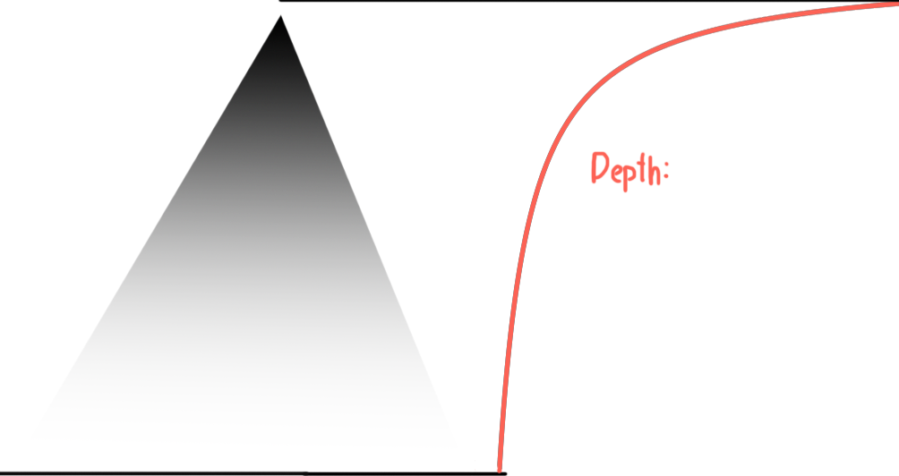
You'll find that by attempting to use the first equation over the latter to calculate depth will result in strange curves when geometry
intersects eachother. The reasoning for this lies in how depth actually effects coordinates. Each x and y value are divided by their depth,
this ends in every x and y value not being transformed equally.
Imagine an ant walking along a triangle, and viewing the projection of that triangle. From the projection's perspective (pun intended)
the ant travels slower and slower as it gets further away, even if it's physically moving the same speed. This shows us how depth is not linear, and thus why we need to find depth differently
than we would with normal vertex attributes.
Shouldn't this depth distortion affect other attributes? Well it does, and you can see the effects and solutions in the next section
We have the ability to take the depth of every pixel, it's time we should compare them. You may find the merging of pixel indexing and depth interpolation in this following code example.
depthArray = floating point array; size [W*H]
timeArray = integer array; size [W*H]
Do every frame
increment current frame
Draw triangles and whatnot
Loop
For every pixel ( x , y ) in a triangle ( x1 , y1 , z1 , x2 , y2 , z2 , x3 , y3 , z3 ) Where z1 , z2 , z3 are the depths of their respective vertex
u = getU ( x1 , y1 , x2 , y2 , x3 , y3 , x , y ) v = getV ( x1 , y1 , x2 , y2 , x3 , y3 , x , y ) w = getW ( x1 , y1 , x2 , y2 , x3 , y3 , x , y ) depth = 1 / ( u / z1 + v / z2 + w / z3 ) index = y * W + x
If depthArray[index] < depth or timeArray[index] < current frame
depthArray[index] = depth
timeArray[index] = current frame
Draw pixel ( x , y )
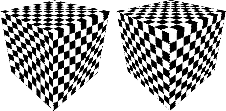
Correcting Barycentric Coordinates with Depth
We are not quite at the finish line, if we use all of these methods, we can draw 3d shapes with no problem. But if we attempt to draw anything on the faces using barycentric coordinates,
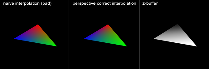
we will find that the triangles appear normal, but everything will look just off every so slightly. This graphic by scratchapixel will show what it would appear like.
You'll see in the image that the triangle on the left appears 2 Dimensional and flat, whereas it's easier to gather the depth from the
second triangle. This is how things will appear after depth correction of the vertex attributes.
This problem is more apparent when using textures because images will hold straight lines, whereas simple gradients might hide misteps.
The reasoning for this distortion is the same as the reason for grabbing depth needing more than simple barycentric interpolation. Fortunately, after grabbing the new depth,
we can compute the new attributes of each pixel rather easily. How we achieve this is by just dividing each vertex attribute by its vertex's depth, then we use barycentric coordinates
to interpolate the resulting values. Then, multiplying them by the current pixel's depth, we have our final attribute.
Equations that show what's going on here would look like this. Where d is the depth of each vertice and of the current pixel, and a is an attribute of a vertex like color or whatnot, and our barycentric coordinates, u, v, and w.
$$d_{pixel} = \frac{1}{\frac{u}{d_1} + \frac{v}{d_2} + \frac{w}{d_3}}$$
$$a_{pixel} = \left(u\frac{a_1}{d_1} + v\frac{a_2}{d_2} + w\frac{a_3}{d_3}\right)d_{pixel}$$
This helps as the attribute not only relies on barycentric coordinates, but also depth. A pixel will not just appear like a vertice as it's barycentric coords approach it, but its depth needs to approach it as well.
The following hypothetical code will
For every pixel ( x , y ) in triangle ( x1 , y1 , z1 , x2 , y2 , z2 , x3 , y3 , z3 ) Where z1 , z2 , z3 are the depth of each vertex
u = getU ( x1 , y1 , x2 , y2 , x3 , y3 , x , y ) v = getV ( x1 , y1 , x2 , y2 , x3 , y3 , x , y ) w = getW ( x1 , y1 , x2 , y2 , x3 , y3 , x , y ) depth = 1 / ( u/z1 + v/z2 + w/z3 ) color = depth * ( RED * u/z1 + GREEN * v/z2 + BLUE * w/z3 )
Putting the Code All Together
The following code will work in QB64
Dim Shared W As Integer , H As Integer
W = 720
H = 480
bscreen = _NewImage ( W , H , 32 ) Screen bscreen
Dim Shared pixelDepth ( W * H ) As Double
Dim Shared pixelTime ( W * H ) As Double
Dim Shared currentFrame As Integer
currentFrame = 0
Dim Shared FOV As Double , Zm As Double , Za As Double
theta# = 90 * 3.14159265 / 180.0 ' 90 is the FOV angle in degrees , theta is in radians
FOV = 1 / Tan ( theta# * 0.5 ) Far = 10000
Near = 0.01
Zm = -Far / ( Far - Near ) Za = - ( Far * Near ) / ( Far - Near ) 'Declare variables for numbers used in multiple Functions and Subs
Dim Shared triX1 , triY1 , triZ1 , triX2 , triY2 , triZ2 , triX3 , triY3 , triZ3
Do
Cls
currentFrame = currentFrame + 1
Call triangle ( -50 , -50 , -100 , 50 , 50 , -100 , 100 , -75 , -200 ) _Display
Loop
Function projectZ ( z As Double ) projectZ = z * Zm + Za
End Function
Function projectX ( x As Double , z As Double ) projectX = ( ( x / z ) * FOV * 0.5 + 0.5 ) * W
End Function
Function projectY ( y As Double , z As Double ) projectY = ( y / z ) * FOV * W * 0.5 + 0.5 * H
End Function
Function getU ( px , py ) ' Compute cross product divided by two
area = ( ( triX3 - triX1 ) * ( triY2 - triY1 ) - ( triY3 - triY1 ) * ( triX2 - triX1 ) ) * 0.5
getU = ( ( triX3 - px ) * ( triY2 - py ) - ( triY3 - py ) * ( triX2 - px ) ) / 2 * area
End Function
Function getV ( px , py ) area = ( ( triX3 - triX1 ) * ( triY2 - triY1 ) - ( triY3 - triY1 ) * ( triX2 - triX1 ) ) * 0.5
getV = ( ( triX1 - px ) * ( triY3 - py ) - ( triY1 - py ) * ( triX3 - px ) ) / 2 * area
End Function
Function getW ( px , py ) area = ( ( triX3 - triX1 ) * ( triY2 - triY1 ) - ( triY3 - triY1 ) * ( triX2 - triX1 ) ) * 0.5
getW = ( ( triX2 - px ) * ( triY1 - py ) - ( triY2 - py ) * ( triX1 - px ) ) / 2 * area
End Function
Sub rasterFlatTriangle ( x1 , y1 , x2 , x3 , term ) 'z1 , z2 , and z3 are the depths of each point
'Declare inverse slops from a to b , and a to c
Dim y As Integer , x As Integer
Dim a_m , b_m , lx , rx , xsign , ysign , bu , bv , bw , depth , index
a_m = ( x2 - x1 ) / ( term - y1 ) b_m = ( x3 - x1 ) / ( term - y1 ) 'Declare the y "scanline" , set it to the terminator and work up to the origin
y = term
'Declare the two x values that walk the lines from the terminator to the origin
lx = x2
rx = x3
'Signs dictate which directions to increment in , +1 or -1
xsign = Sgn ( rx - lx ) ysign = Sgn ( y1 - term ) Do
x = lx
If y < 0 Or y >= H Then
GoTo skipy
End If
Do
bu = getU ( x , y ) bv = getV ( x , y ) bw = getW ( x , y ) depth = 1 / ( bu / triZ1 + bv / triZ2 + bw / triZ3 ) index = ( y * W ) + x
If x < 0 Or x >= W Then
GoTo skipx
End If
If pixelDepth ( index ) < depth Or pixelTime ( index ) < currentFrame Then
pixelDepth ( index ) = depth
pixelTime ( index ) = currentFrame
Color _RGB ( 255 * bu / triZ1 * depth , 255 * bv / triZ2 * depth , 255 * bw / triZ3 * depth ) 'Color _RGB ( 255 , 255 , 0 ) PSet ( x , y ) 'Set the pixel! ( QB64 method , requires 32 bit screen mode ) End If
skipx:
x = x + xsign
Loop While ( ( xsign = 1 And x < rx ) Or ( xsign = -1 And x > rx ) ) skipy:
y = y + ysign
lx = lx + a_m * ysign
rx = rx + b_m * ysign
Loop While ( ( ysign = 1 And y < y1 ) Or ( ysign = -1 And y > y1 ) ) End Sub
Sub triangle ( x1 , y1 , z1 , x2 , y2 , z2 , x3 , y3 , z3 ) 'Find 2d coordinates + depth from original coordinates
Dim m
triZ1 = projectZ ( z1 ) triX1 = projectX ( x1 , triZ1 ) triY1 = projectY ( y1 , triZ1 ) triZ2 = projectZ ( z2 ) triX2 = projectX ( x2 , triZ2 ) triY2 = projectY ( y2 , triZ2 ) triZ3 = projectZ ( z3 ) triX3 = projectX ( x3 , triZ3 ) triY3 = projectY ( y3 , triZ3 ) 'If any two y coordinates are equal , then draw a flat triangle
If triY1 = triY2 Then
Call rasterFlatTriangle ( triX3 , triY3 , triX1 , triX2 , triY1 ) : GoTo triangleskip
ElseIf triY2 = triY3 Then
Call rasterFlatTriangle ( triX1 , triY1 , triX2 , triX3 , triY2 ) : GoTo triangleskip
ElseIf triY3 = triY1 Then
Call rasterFlatTriangle ( triX2 , triY2 , triX1 , triX3 , triY1 ) : GoTo triangleskip
End If
'Find the middle y-coordinate and split the triangle into 2 flat triangles
If ( triY1 < triY2 And triY1 > triY3 ) Or ( triY1 > triY2 And triY1 < triY3 ) Then
m = triX2 + ( triY1 - triY2 ) * ( triX3 - triX2 ) / ( triY3 - triY2 ) Call rasterFlatTriangle ( triX3 , triY3 , triX1 , m , triY1 ) Call rasterFlatTriangle ( triX2 , triY2 , triX1 , m , triY1 ) GoTo triangleskip
ElseIf ( triY2 < triY1 And triY2 > triY3 ) Or ( triY2 > triY1 And triY2 < triY3 ) Then
m = triX1 + ( triY2 - triY1 ) * ( triX3 - triX1 ) / ( triY3 - triY1 ) Call rasterFlatTriangle ( triX3 , triY3 , triX2 , m , triY2 ) Call rasterFlatTriangle ( triX1 , triY1 , triX2 , m , triY2 ) GoTo triangleskip
ElseIf ( triY3 < triY1 And triY3 > triY2 ) Or ( triY3 > triY1 And triY3 < triY2 ) Then
m = triX1 + ( triY3 - triY1 ) * ( triX2 - triX1 ) / ( triY2 - triY1 ) Call rasterFlatTriangle ( triX2 , triY2 , triX3 , m , triY3 ) Call rasterFlatTriangle ( triX1 , triY1 , triX3 , m , triY3 ) End If
triangleskip:
End Sub
While the given code above will run, it isn't that exciting. There are many adjustments we can make to give more to look at, as well as adjustments we can make to
speed up rendering quite substantially.
Firstly, one of the biggest changes you can make to improve the look of a 3d program is to introduce rotation. Without it you would be stuck moving a still shape across the screen. Rotation is mathematically tedius,
but it's much easier to understand with Matrix Transformation. If you take a vector as a point in 3d space, you can rotate it around the origin (0, 0, 0) with the following (column vector) matrices.
$$R_x(\theta) = \begin{bmatrix}1 & 0 & 0\\0 & cos\theta & sin\theta\\0 & -sin\theta & cos\theta\end{bmatrix}$$
$$R_y(\theta) = \begin{bmatrix}cos\theta & 0 & -sin\theta\\0 & 1 & 0\\sin\theta & 0 & cos\theta\end{bmatrix}$$
$$R_z(\theta) = \begin{bmatrix}cos\theta & sin\theta & 0\\-sin\theta & cos\theta & 0\\0 & 0 & 1\end{bmatrix}$$
What each of these mean is that, say for \(R_x(\theta)\), given angle \(\theta\), the transformation will rotate a vector around the X axis by this angle. Thus there are 3 axes of rotation, each around
their respective 3D axis.
(In order left-to-right: X-rotation; Y-rotation; Z-rotation)
Combining these matrices, you end up with one matrix you can use to rotate any vector in all 3 axes at the same time;
$$R_{xyz}(\alpha, \beta, \gamma) = \begin{bmatrix}\cos\alpha \cos\beta & \sin\alpha \cos\beta & -\sin\beta \\ \cos\alpha \sin\beta \sin\gamma - \sin\alpha \cos\gamma & \sin\alpha \sin\beta \sin\gamma + \cos\alpha \cos\gamma & \cos\beta \sin\gamma \\ \cos\alpha \sin\beta \cos\gamma + \sin\alpha \sin\gamma & \sin\alpha \sin\beta \cos\gamma - \cos\alpha \sin\gamma & \cos\beta \cos\gamma \end{bmatrix}$$
Where \(\alpha\) is the angle around the Z axis, \(\beta\) around the Y axis, and \(\gamma\) around the X axis. Implementing this into BASIC is rather easy, but it is also rather tedious as there
is no easy way to simplify the computations. However, we can make our code a little neater and clean using a User Defined Type (UDT). Like a struct or class for QBASIC.
We will create a UDT called "vector". It will store 4 numbers, for an x, y, z and w coordinate.
And as we cannot return more than one number per function, (i.e, we cannot return a UDT in QB64, we can only return a built-in type, like a number or string), we will set a universal vector the be the set "output"
of some functions. Given all that, let me show you what our rotation function will look like, with a vector UDT defined.
Type vector
x As Single
y As Single
z As Single
w As Single
End Type
Dim Shared vector As vector
'Set the position you want to rotate
vector.x = 1
vector.y = 2
vector.z = -1
vector.w = 0
'Call the rotation function , the given parameters will rotate it 90 degrees around the y axis
Call rotateVector ( 0 , 3.1459265 / 2 , 0 ) Print vector.x , vector.y , vector.z , vector.w
' Prints 1 2 1 0
Sub rotateVector ( rx As Single , ry As Single , rz As Single ) Dim nvector As vector
nvector.x = ( vector.x * Cos ( rz ) * Cos ( ry ) ) + ( vector.y * Sin ( rz ) * Cos ( ry ) ) - vector.z * Sin ( ry ) nvector.y = ( vector.x * ( Cos ( rz ) * Sin ( ry ) * Sin ( rx ) - Sin ( rz ) * Cos ( rx ) ) ) + ( vector.y * ( Sin ( rz ) * Sin ( ry ) * Sin ( rx ) + Cos ( rz ) * Cos ( rx ) ) ) + ( vector.z * Cos ( ry ) * Sin ( rx ) ) nvector.z = ( vector.x * ( Cos ( rz ) * Sin ( ry ) * Cos ( rx ) + Sin ( rz ) * Sin ( rx ) ) ) + ( vector.y * ( Sin ( rz ) * Sin ( ry ) * Cos ( rx ) - Cos ( rz ) * Sin ( rx ) ) ) + ( vector.z * Cos ( ry ) * Cos ( rx ) ) vector.x = nvector.x: vector.y = nvector.y: vector.z = nvector.z: vector.w = 1
End Sub
In order to substantially speed up the program, we can think about all the computations happening in our program, and thinking about their necessity and how it
might be possible to cut things down. If we look at an outline of the program so far, we can see some critical points where computation is heavy.
For every triangle:
Call projection for every coordinate of all 3 points
Find flat triangles
For each flat triangle:
Calculate the slopes of the sides of the flat triangle
For every y value in the triangle's y value range:
Increment ends of x range by their slopes
For every pixel in the triangle:
Calculate u, v, and w barycentric coordinates
Calculate depth (and index) of current pixel
Compare to depth and time array
Draw pixel
Through this we can see that the heaviest load is during the pixel drawing process. As those calculations are repeated the most often: For every pixel in every triangle.
But it seems as though we can't clean it up any further without sacrificing depth testing and barycentric coordinates. However, we can still simplify it using derivatives.
Take our barycentric coordinate calculations. They seem pretty complicated, however note that the only thing changing in them is the x and the y position of the pixel. And each time the values change, they change by exactly 1.
If we use the derivative of these equations in respect to x and y, and depending on what we're incrementing at that current moment, add them to running barycentric coordinate variables.
Given our UVW calculations:
$$u = \frac{\left(x_3-p_x\right) * \left(y_2-p_y\right) - \left(y_3-p_y\right) * \left(x_2-p_x\right)}{2a}$$
$$v = \frac{\left(x_1-p_x\right) * \left(y_3-p_y\right) - \left(y_1-p_y\right) * \left(x_3-p_x\right)}{2a}$$
$$w = \frac{\left(x_2-p_x\right) * \left(y_1-p_y\right) - \left(y_2-p_y\right) * \left(x_1-p_x\right)}{2a}$$
We find that the derivatives of such in respect to x and y are as follows:
$$\frac{du}{dx} = \frac{y_3-y_2}{2a}$$
$$\frac{dv}{dx} = \frac{y_1-y_3}{2a}$$
$$\frac{dw}{dx} = \frac{y_2-y_1}{2a}$$
$$\frac{du}{dy} = \frac{x_2-x_3}{2a}$$
$$\frac{dv}{dy} = \frac{x_3-x_1}{2a}$$
$$\frac{dw}{dy} = \frac{x_1-x_2}{2a}$$
Given that these computations only rely on the positions of the three vertices of the triangle, they can be calculated once per triangle.
Whenever we increment x, we must increment u by 'du/dx' times what our change in x is, typically 1, and the same goes for increments in y with 'du/dy'.
It is possible to take and use the derivative of the depth calculation, however it would be more trouble than it's worth.
Given rotation and our optimization, below you'll find yet another fully working version of this project. Using arrow keys to control rotation.
Type vector
x As Double
y As Double
z As Double
w As Double
End Type
Dim Shared As Integer Width , Height
Dim Shared As Single triX1 , triX2 , triX3 , triY1 , triY2 , triY3 , tri1OverZ1 , tri1OverZ2 , tri1OverZ3 , triArea , tri1OverArea , triU , triV , triW
Dim Shared vector as vector
Dim Shared projection_data ( 4 ) As Double ' Store FOV * 0.5 , FOV * Width * 0.5 , Zm , and Za
Dim Shared As Single lslope , rslope , lx , rx , sy , ey , dudx , dvdx , dwdx , dudy , dvdy , dwdy , pixel_index , depth
Dim Shared pixel_x As Integer
Dim Shared pixel_y As Integer
Dim Shared current_frame As Integer
current_frame = 1
Width = 800
Height = 800
Dim Shared pixel_depth ( Width * Height ) As Double
Dim Shared pixel_time ( Width * Height ) As Double
display = _NewImage ( Width , Height , 32 ) Screen display
Call setProjection ( 90 , 10000 , 0.01 ) positionx = 0
positiony = 0
positionz = -200
rotationx = 0.0
rotationy = 0.0
Do
Cls
If _KeyDown ( 19200 ) Then
rotationy = rotationy - 0.03
End If
If _KeyDown ( 19712 ) Then
rotationy = rotationy + 0.03
End If
If _KeyDown ( 18432 ) Then
rotationx = rotationx + 0.03
End If
If _KeyDown ( 20480 ) Then
rotationx = rotationx - 0.03
End If
Call cube ( positionx , positiony , positionz , 50 , rotationx , rotationy ) current_frame = current_frame + 1
_Display
Loop
Color _RGB ( 255 , 255 , 255 ) End
Sub cube ( positionx As Single , positiony As Single , positionz As Single , size As Single , rotationx As Single , rotationy As Single ) Dim As vector lft , rft , lbt , rbt , lfb , rfb , lbb , rbb
setVector -size , size , -size , 0
rotateVector rotationx , rotationy , 0
lft.x = vector.x + positionx: lft.y = vector.y + positiony: lft.z = vector.z + positionz
setVector size , size , -size , 0
rotateVector rotationx , rotationy , 0
rft.x = vector.x + positionx: rft.y = vector.y + positiony: rft.z = vector.z + positionz
setVector -size , size , size , 0
rotateVector rotationx , rotationy , 0
lbt.x = vector.x + positionx: lbt.y = vector.y + positiony: lbt.z = vector.z + positionz
setVector size , size , size , 0
rotateVector rotationx , rotationy , 0
rbt.x = vector.x + positionx: rbt.y = vector.y + positiony: rbt.z = vector.z + positionz
setVector -size , -size , -size , 0
rotateVector rotationx , rotationy , 0
lfb.x = vector.x + positionx: lfb.y = vector.y + positiony: lfb.z = vector.z + positionz
setVector size , -size , -size , 0
rotateVector rotationx , rotationy , 0
rfb.x = vector.x + positionx: rfb.y = vector.y + positiony: rfb.z = vector.z + positionz
setVector -size , -size , size , 0
rotateVector rotationx , rotationy , 0
lbb.x = vector.x + positionx: lbb.y = vector.y + positiony: lbb.z = vector.z + positionz
setVector size , -size , size , 0
rotateVector rotationx , rotationy , 0
rbb.x = vector.x + positionx: rbb.y = vector.y + positiony: rbb.z = vector.z + positionz
tri_vector lft , rft , rfb
tri_vector rfb , lfb , lft
tri_vector rbt , lbt , lbb
tri_vector lbb , rbb , rbt
tri_vector lbt , lft , lfb
tri_vector lfb , lbb , lbt
tri_vector rft , rbt , rbb
tri_vector rbb , rfb , rft
tri_vector rft , lbt , rbt
tri_vector lbt , rft , lft
tri_vector lfb , rbb , lbb
tri_vector rbb , lfb , rfb
End Sub
' Returns the max between two numbers
Function max ( ma_x , ma_y ) max = ma_x
If ma_y > ma_x Then
max = ma_y
End If
End Function
' Returns the min between two numbers
Function min ( mi_x , mi_y ) min = mi_x
If mi_y < mi_x Then
min = mi_y
End If
End Function
Sub setVector ( x As Double , y As Double , z As Double , w As Double ) vector.x = x
vector.y = y
vector.z = z
vector.w = w
End Sub
Sub setProjection ( FOVAngle As Double , Far As Double , Near As Double ) projection_data ( 0 ) = 0.5 / Tan ( FOVAngle * 3.14159267 / 360.0 ) projection_data ( 1 ) = Width * projection_data ( 0 ) projection_data ( 2 ) = -Far / ( Far - Near ) projection_data ( 3 ) = - ( Far * Near ) / ( Far - Near ) End Sub
Sub projectVector ' Leaves z as 1/z
vector.z = 1 / ( vector.z * projection_data ( 2 ) + vector.w * projection_data ( 3 ) ) vector.x = vector.x * vector.z * projection_data ( 1 ) + vector.w * 0.5 * Width
vector.y = vector.y * vector.z * projection_data ( 1 ) + vector.w * 0.5 * Height
End Sub
Sub rotateVector ( rx As Double , ry As Double , rz As Double ) Dim nvector As vector
nvector.x = ( vector.x * Cos ( rz ) * Cos ( ry ) ) + ( vector.y * Sin ( rz ) * Cos ( ry ) ) - vector.z * Sin ( ry ) nvector.y = ( vector.x * ( Cos ( rz ) * Sin ( ry ) * Sin ( rx ) - Sin ( rz ) * Cos ( rx ) ) ) + ( vector.y * ( Sin ( rz ) * Sin ( ry ) * Sin ( rx ) + Cos ( rz ) * Cos ( rx ) ) ) + ( vector.z * Cos ( ry ) * Sin ( rx ) ) nvector.z = ( vector.x * ( Cos ( rz ) * Sin ( ry ) * Cos ( rx ) + Sin ( rz ) * Sin ( rx ) ) ) + ( vector.y * ( Sin ( rz ) * Sin ( ry ) * Cos ( rx ) - Cos ( rz ) * Sin ( rx ) ) ) + ( vector.z * Cos ( ry ) * Cos ( rx ) ) nvector.w = 1
vector.x = nvector.x: vector.y = nvector.y: vector.z = nvector.z
End Sub
Sub tri_flat_term ( x1 , y1 , x2 , x3 , term ) lx = x2 ' Set left x that will be walking line ( x2 , term ) - ( x1 , y1 ) rx = x3 ' Set right x that will be walking line ( x3 , term ) - ( x1 , y1 ) If ( x2 > x3 ) Then
rx = x2: lx = x3
End If
lslope = ( lx - x1 ) / ( term - y1 ) ' Negative left inverse slope depending on if y will be increasing or decreasing
rslope = ( rx - x1 ) / ( term - y1 ) ' Negative right inverse slope for same reason
' Set starting y and ending y
sy = term
ey = y1
If ( y1 < term ) Then
sy = y1: ey = term: lx = x1: rx = x1
End If
' Set uvw
triU = ( ( triX3 - lx ) * ( triY2 - sy ) - ( triY3 - sy ) * ( triX2 - lx ) ) * 0.5 * tri1OverArea
triV = ( ( triX1 - lx ) * ( triY3 - sy ) - ( triY1 - sy ) * ( triX3 - lx ) ) * 0.5 * tri1OverArea
triW = ( ( triX2 - lx ) * ( triY1 - sy ) - ( triY2 - sy ) * ( triX1 - lx ) ) * 0.5 * tri1OverArea
' Set duvw/dx
dudx = ( triY3 - triY2 ) * 0.5 * tri1OverArea
dvdx = ( triY1 - triY3 ) * 0.5 * tri1OverArea
dwdx = ( triY2 - triY1 ) * 0.5 * tri1OverArea
' Set duvw/dy
dudy = ( triX2 - triX3 ) * 0.5 * tri1OverArea
dvdy = ( triX3 - triX1 ) * 0.5 * tri1OverArea
dwdy = ( triX1 - triX2 ) * 0.5 * tri1OverArea
For pixel_y = sy To ey - 1
If pixel_y < 0 Or pixel_y >= Height Then
GoTo tri_flat_term_yskip
End If
For pixel_x = lx To rx
triU = triU + dudx
triV = triV + dvdx
triW = triW + dwdx
If pixel_x < 0 Or pixel_x >= Width Then
GoTo tri_flat_term_xskip
End If
pixel_index = pixel_y * Width + pixel_x
depth = 1 / ( triU * tri1OverZ1 + triV * tri1OverZ2 + triW * tri1OverZ3 ) If pixel_depth ( pixel_index ) > depth Or pixel_time ( pixel_index ) < current_frame Then
pixel_depth ( pixel_index ) = depth
pixel_time ( pixel_index ) = current_frame
Color _RGB ( triU * 256 , triV * 256 , triW * 256 ) PSet ( pixel_x , pixel_y ) End If
tri_flat_term_xskip:
Next
tri_flat_term_yskip:
triU = triU + dudy + lslope * dudx - ( CInt ( rx ) - CInt ( lx ) + 1 ) * dudx
triV = triV + dvdy + lslope * dvdx - ( CInt ( rx ) - CInt ( lx ) + 1 ) * dvdx
triW = triW + dwdy + lslope * dwdx - ( CInt ( rx ) - CInt ( lx ) + 1 ) * dwdx
lx = lx + lslope
rx = rx + rslope
Next
End Sub
Sub tri ( x1 , y1 , z1 , x2 , y2 , z2 , x3 , y3 , z3 ) 'Project all 3 vertices to pixel-coordinates
setVector x1 , y1 , z1 , 1
projectVector
triX1 = vector.x: triY1 = vector.y: tri1OverZ1 = vector.z
setVector x2 , y2 , z2 , 1
projectVector
triX2 = vector.x: triY2 = vector.y: tri1OverZ2 = vector.z
setVector x3 , y3 , z3 , 1
projectVector
triX3 = vector.x: triY3 = vector.y: tri1OverZ3 = vector.z
' Compute extra triangle data
triArea = ( ( triX3 - triX1 ) * ( triY2 - triY1 ) - ( triY3 - triY1 ) * ( triX2 - triX1 ) ) * 0.5
tri1OverArea = 1 / triArea
' if any of the y coordinates are the same , draw a flat terminating triangle instead of splitting it
If triY1 = triY2 Then
tri_flat_term triX3 , triY3 , triX1 , triX2 , triY1: GoTo tri_skip
ElseIf triY2 = triY3 Then
tri_flat_term triX1 , triY1 , triX2 , triX3 , triY2: GoTo tri_skip
ElseIf triY3 = triY1 Then
tri_flat_term triX2 , triY2 , triX3 , triX1 , triY3: GoTo tri_skip
End If
Dim m
' Check which vertice is in the middle of the triangle in terms of y
If ( triY1 < triY2 And triY1 > triY3 ) Or ( triY1 > triY2 And triY1 < triY3 ) Then
m = triX2 + ( triY1 - triY2 ) * ( triX3 - triX2 ) / ( triY3 - triY2 ) tri_flat_term triX3 , triY3 , triX1 , m , triY1: tri_flat_term triX2 , triY2 , triX1 , m , triY1: GoTo tri_skip
ElseIf ( triY2 < triY1 And triY2 > triY3 ) Or ( triY2 > triY1 And triY2 < triY3 ) Then
m = triX1 + ( triY2 - triY1 ) * ( triX3 - triX1 ) / ( triY3 - triY1 ) tri_flat_term triX3 , triY3 , triX2 , m , triY2: tri_flat_term triX1 , triY1 , triX2 , m , triY2: GoTo tri_skip
Else
m = triX1 + ( triY3 - triY1 ) * ( triX2 - triX1 ) / ( triY2 - triY1 ) tri_flat_term triX2 , triY2 , triX3 , m , triY3: tri_flat_term triX1 , triY1 , triX3 , m , triY3
End If
tri_skip:
End Sub
Sub tri_vector ( a As vector , b As vector , c As vector ) tri a.x , a.y , a.z , b.x , b.y , b.z , c.x , c.y , c.z
End Sub
It's great having a real-time example of 3d graphics built in BASIC, but what if we wanted to do more? If we had no regard for speed, what could we accomplish with what we've made?
You might recall earlier in this paper when I provided images of cubes displaying textures. How exactly do we make this possible, and what more does that allow us to do?
More often than not, barycentric coordinates are used to interpolate between texture coordinates. Unhelpfully denoted with U and V. (Sometimes even W.) This coordinate
system is used to represent points on an image, typically spanning from 0 to 1.
If we give our barycentric coordinates texture coordinates to interpolate, we can take the resulting texture coordinate and use it to grab a color from an image.
We can then draw this color directly to the screen, or we can do more processing with it.
A lot of modern graphics rely on clever usage of textures in order to create different lighting conditions and produce a pixel based on a combination of
factors. And this is most commonly done through shaders.
A shader is a routine that is used to transform a set of input values to output values for the sake of 3d rendering. There are different types of shaders:
vertex shaders which take in vertex attributes and tells the computer where it should lie on the screen or raster, geometry shaders which take in as much as whole
3d shapes and is able to transform existing and create new geometry, and finally fragment shaders, which take in anything given to them and output a color that
is pushed to the raster. We have already done the work of the vertex shader, don't really need geometry shaders in our example, and pushing the barycentric
coordinates to the screen is enough to constitute as a fragment shader, but lets push it further.
Fragment shaders can do as little as giving the same color to every pixel it's assigned to, or as complicated as simulating virtual light to immitate
realistic lighting as best it can. All the abilities are covered quite in depth elsewhere, so I won't be digging deeper into lighting. However, take note
that QB64 allows you to load textures and access their colors, and these colors can be used to manipulate normal vectors and control how strong lighting effects are.
So take this last piece of BASIC code with you, and go learn more about the concepts of 3D rendering.
For more on shading, from simple to complex 3D lighting: LearnOpenGL
While centered on OpenGL, LearnOpenGL provides a lot more details behind plenty of shading techniques Basic lighting Lighting maps Normal Mapping